Yaskawa Motoman
This page is a guide to help users understand the requirements of setting up a Yaskawa Motoman robotic welding system for use with AutoaWeld. Autoa also offer consulting and training services to assist with the calibration and setup of a welding system - please contact us for pricing.
TCP Calibration
The real world TCP should be calibrated using the Yaskawa tool calibration. After calibration, it is then suggested that the rotational values are overwritten with theoretical values (that can be supplied by Autoa) as rotational values are difficult to calibrate using this method.
Care should be taken to ensure that the axes directions follow the expected directions for AutoaWeld:
- Z - Pointing out in the wire direction.
- X - Pointing up from the robot when the robot is at position
[0, 0, 0, 0, 0, 0]. (This will be pointing out for the MH50-20). - Y - Orthogonal to X and Z with a right hand rule.
The TCP calibration should use the expected stickout specified in the workcell model file supplied by Autoa for the cell and the wirecut routine should be written to cut the wire to this length prior to touch sensing.
Workpiece Positioner Calibration
Headstock Tailstock Axis
The headstock and tailstock position should be known such that the axis direction between the headstock and tailstock can be calculated. Depending on the setup, the inbuilt 'Robot Calibration' function on the Yaskawa controller may be able to calibrate these positions with high enough accuracy for the purpose of offline programming with AutoaWeld. In some cases this may require a slightly different calibration method. Autoa may also supply these values to overwrite any existing values in the robot.
Controller Setup
AutoaWeld requires the following options to be enabled on your controller:
- Master Tool Frame (for synchronised positioner and tool movements).
- Welding functionality created using Arc Start Files and Arc End Files.
- Weaving functionality created using Weaving Files.
This list is not exhaustive.
It is also suggested that the P-variables space is maximised (including Base and External Axis) to allow large programs to be created with AutoaWeld.
Code Output
AutoaWeld is capable of creating a Yaskawa / Motoman Job file(s) (.jbi) that can be loaded and executed by your robot. The code output consists of the following parts:
- The output created by the software for the specific AutoaWeld project.
- Routines (Jobs) supplied by Autoa to perform specific functions. These should not be changed by the end user or system integrator .
- Placeholder routines that are called at certain events (e.g. torch-clean). These are required and can be supplied blank by Autoa. These should contain specific code to perform certain functions, and allow the system integrator (or end user) to create customised functions.
Overall Structure
The structure of the output is:
- Initialisation of P-variables.
- Wirecut.
- Touchsense(s).
- Weld(s).
- Touchsense(s).
- Weld(s).
- â¦
The touch sense code has the following structure:
The weld(s) will follow this format (with touch sense active):
Helping Routines
The code output is supported by other routines that are supplied with the software. Typically these should not be modified:
VBSEARCH- Performs a touch sense search action based on the touch sense data output into the program.VBOFFS- Offsets a point by a supplied distance in the direction of a supplied vector.VBSFT- Creates a robot shift using theSFTONinstruction.VBSSFT- Creates a robot shift using theSSFTONinstruction.
Other Routines
The code output will call these routines at certain events in the code output. All routines are required, but can be empty and simply return upon executing. These should be modified as required by the system integrator to perform the required customised functions.
The following routine events are created:
VBCUTWIRE- Called when a wire-cut is to be performed. This is usually before a group of touch sense operations. This should start and end with the robot in the home position (excluding external axes).VBTORCHCLEAN- Called when a torch-clean is to be performed. Should also include a wire cut. This should start and end with the robot in the home position (excluding external axes).VBBEFORESEARCH- Called before a search is initiated.VBAFTERSEARCH- Called when a search is completed.VBBEFOREWELD- Called before a weld is started.VBAFTERWELD- Called when a weld is completed.
For example, if your welding torch had a wire brake to assist with touch sensing. The VBCUTWIRE routine could be used to switch on the wire brake, and the VBBEFOREWELD routine could be used to switch off the wire brake.
Code Touch-up
During commissioning, the output program points modified like any other program created on the teach pendant. Transition motions use MOVJ command and can be modified, or additional points added.
Where touch sensing is active, AutoaWeld uses reference points (REFP or SREFP) to pass some points to other routines.
REFP8is used to pass the touch sense points toVBSEARCH.REFP8(SREFP8) is used as the weld targets where touch sense is enabled. These points should be modified if required.
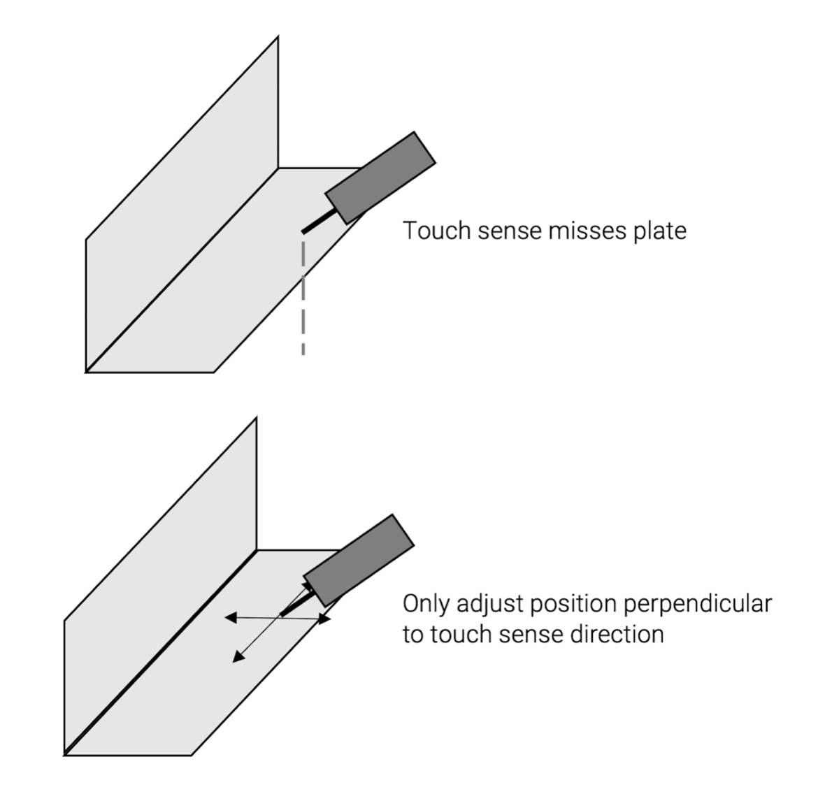
The reference points in the touch sense direction also have information regarding the expected distance to the touch such that the positional difference can be compensated for. If modifying these points care should be taken to only adjust the position perpendicular to the touch direction. The modified point should still touch the intended feature, if unsure please review the simulation for that weld.
Touch sense adjustmentï